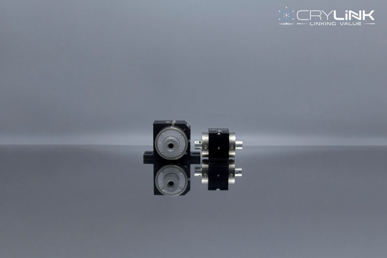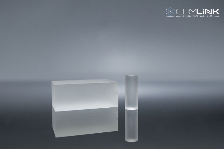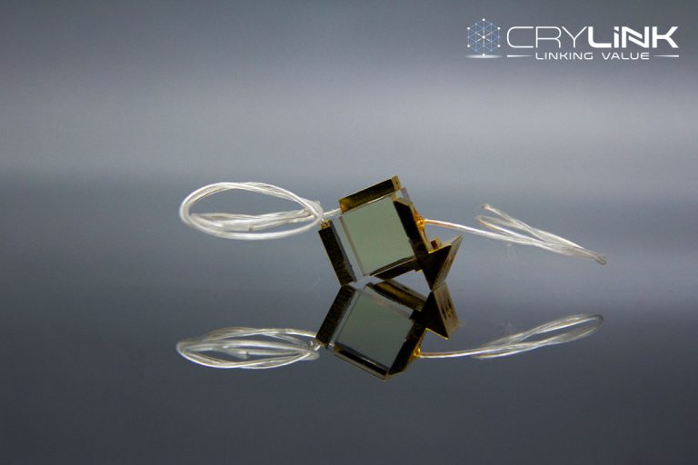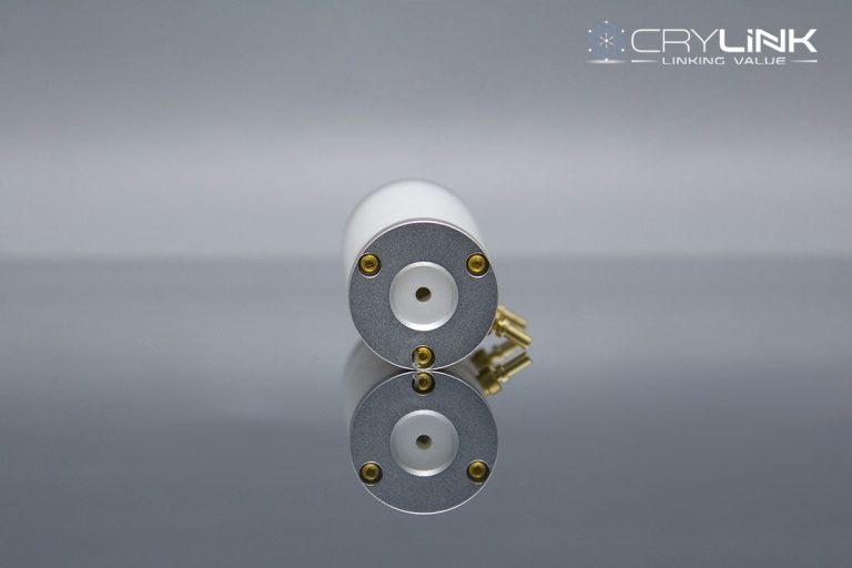
CRYLINK’s pockels cell use a protective window with a high-quality AR coating, ensuring a high transmission rate and prolonging the device’s service life.
By applying electric field control to the electro-optic crystal, the refractive index of the electro-optic crystal in a specific direction can be changed so that the electro-optic modulator pockels cell can be used as a variable half-wave plate to change the polarization state. When the pockels cell of the electro-optic modulator are placed between two vertical polarizers, the luminous intensity modulation can be realized. The electro-optic effect can be divided into the transverse and longitudinal electro-optic effects. In the transverse electro-optic effect, the propagation direction of light is perpendicular to the electric field, and the propagation direction of light in the longitudinal electro-optic effect is parallel to the electric field.
The half-wave voltage of the longitudinal electro-optic effect is independent of crystal size, so it is challenging to realize high-frequency electro-optic modulation. The working principle of BBO pockels cell is based on the transverse electro-optic effect. The half-wave voltage can be reduced by changing the size of BBO crystal. Crylink can provide BBO pockels cell with different aperture and lengths, adapting to different environments. Due to its low ringing effect and high laser-damaged threshold, the maximum frequency of Crylink’s BBO pockels cell can reach 1MHz.
- Low ringing effect
- Low insertion loss
- Small and compact
- Multi wavelength selection
- High laser-damaged threshold
- High repetition rate DPSS Q-switch
- Pulse selection
- High repetition rate regenerative amplifier control
- Cavity dumping
- High frequency optical switch
- Beam chopper
- Optical power stabilizer
Parameter
Product Model | Clear Aperture (mm) | Shell Size | λ/4Voltage (@ 1064 nm), kV DC | Capacitance, pF |
| CLBBO-S02525-2035 | 2.2 | Dia. 20×35 mm | 2.4kV | 2.2pF |
| CLBBO-S02525-151728-S | 2.2 | 15×17.5×28 mm Square enclosure | 2.4kV | 2.2pF |
| CLBBO-S0320-2035 | 2.7 | Dia.20×35 mm | 3.6kV | 3pF |
| CLBBO-S0325-2035 | 2.7 | Dia.20×35 mm | 2.9kV | 3pF |
| CLBBO-S0420-2035 | 3.7 | Dia.20×35 mm | 4.8kV | 4pF |
| CLBBO-S0425-2035 | 3.7 | Dia.20×35 mm | 3.9kV | 4pF |
PS: Transmittance: >99%; Use wavelength: 1030 nm-1064 nm; Resist light damage,10ns 10Hz 1064 nm: 600MW/cm2; Extinction Ratio: 1000:1
Product Model | Clear Aperture (mm) | Shell Size | λ/4Voltage (@ 1064 nm), kV DC | Capacitance, pF |
| CLBBO-D0320-2055 | 2.7 | Dia.20×55 mm | 1.8kV | 6pF |
| CLBBO-D0420-2055 | 3.7 | Dia.20×55 mm | 2.4kV | 7pF |
PS: Transmittance: >99%; Use wavelength: 1030 nm-1064 nm; Resist light damage,10ns 10Hz 1064 nm: 600MW/cm2; Extinction Ratio: 300:1
| Clear Aperture | To be confirmed |
| Transmittance | >98% |
| Damage Threshold | 500MW/cm2@10ns 1064nm |
| Wavefront Distortion | <λ/8 @1064nm |
| Typical Capacitance | <3pF |
| Shell Size | φ25.4×44mm |
| Quarter-wave Voltage | 3.4kv |
| Crystal Structure | Trigonal,space group R3c,point group 3m |
| Lattice Constant | a=b=12.532Å,c=12.717Å,Z=6 |
| Melting Point | 1095±5℃ |
| Phase Transformation Point | 925±5℃ |
| Optical Homogeneity | δn~10-6cm |
| Mohs Hardness | 4 |
| Density | 3.85g/cm3 |
| Hygroscopicity | Low |
| Thermal Coefficient of Expansion | a:4×10⁻⁶K,c:36×10-6K |
| Thermal Conductivity | ⊥C:1.2W/m/k , ∥C:1.6W/m/K |
| Absorption Coefficient | <0.1%/cm @1064nm |
| Transparency Range | 189-3500nm |
| Refractive Index | 1064nm no=1.6545,ne=1.5392 |
| 800nm no=1.6606,ne=1.5444 | |
| 532nm no=1.6742,ne=1.5547 | |
| 400nm no=1.6930,ne=1.5679 | |
| Thermo-optical Coeffecient | dno/dT=-9.3×10-6/℃ |
| dne/dT=-16.6×10-6/℃ | |
| Electro-optic Coefficient | γ11=2.7pm/V,γ22,γ31<0.1γ11 |
| Half-wave Voltage | 48KV @1064nm |
| NLO Coefficient | d11=5.8×d36(KDP) |
| d31=0.05×d11 | |
| d22<0.05×d11 | |
| Phase Matching SH Wavelength | 189-3500nm |

