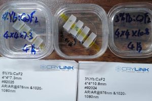
Crystals usually need to be cut along a certain crystal plane direction when cutting. In order to prepare to remove a certain crystal plane, we propose this technical solution for actual cutting applications, which can conveniently and accurately cut the required crystal plane.
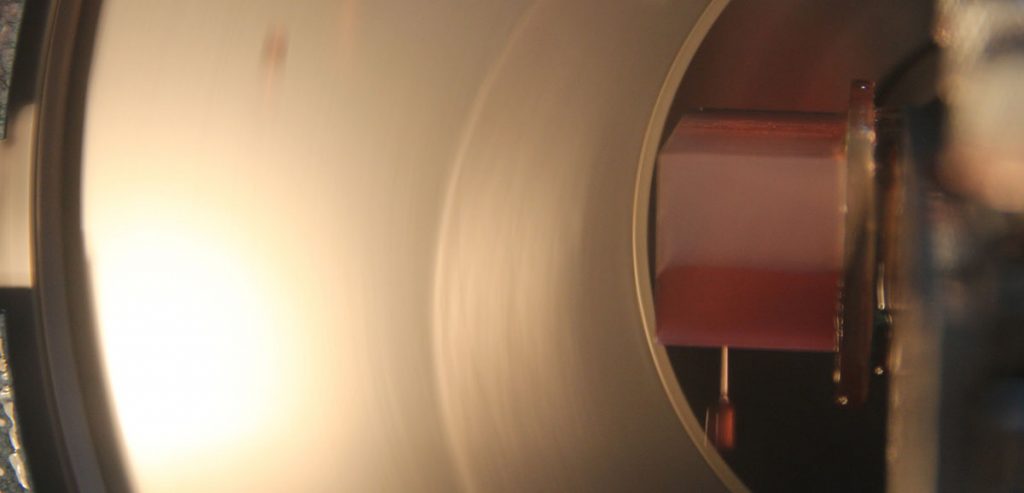
(1) First, perform preliminary orientation rough grinding on each crystal plane to be cut to ensure that it can be accurately oriented within ±30′.
(2) Glue the crystal to the board according to the cutting requirements, and set rough-grind surface face to the knife.
(3) Cut a small slice from the head, mark the top, bottom, left, and right, and then orient the cutting surface in the up, down, left, and right directions, and record the deviation from the standard value in each direction (such as left and right deviation ±15′, up and down deviation ±20′, etc. ).
(4) Calculate the calibration distance: fix the laser, aim at the glass sheet on the tool holder, let the reflected light spot fall on the appropriate position on the opposite wall (ensure sufficient adjustment space), and then calculate the actual distance to be adjusted ( If the left-right deviation is 15′ in step 3, the distance that needs to be adjusted is 32*15*2=69.6mm; the up-down deviation is 20′, the distance that needs to be adjusted is 2.32*20*2=92.8mm).
(5) Mark the calibration point, use the light spot as the origin to determine the calibration offset direction according to the deviation direction, draw a straight line on the wall in this direction, and mark the adjustment distance, such as marking 6mm to the left or right in the horizontal direction. Then draw a straight line up or down in the vertical direction using this as a reference point, and mark the adjustment distance of 92.8mm.
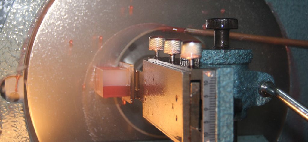
(6) Calibrate the cutting direction: loosen the fastening screw of the material plate in the horizontal direction, slowly adjust the material plate, so that the light spot moves to the marked position along the marking line in the horizontal direction, and fix the screw. Then, loosen the fastening screws of the material plate in the vertical direction, slowly adjust the material plate, so that the light spot slowly moves to the marked point along the vertical marking line, and after alignment, tighten the screw. The cutting direction calibration is over.
(7) Cut a small slice according to the calibrated cutting direction, and then verify the orientation of the new cutting surface. If the upper and lower left and right directions of the new cutting surface are consistent with the standard surface or the deviation is within the cutting deviation range, you can follow this The cutting direction cuts the crystal. If the deviation is large, you need to calibrate again according to the above method, and finally make the deviation of the cutting surface direction meet the cutting requirements.
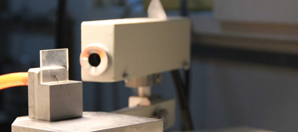
(8) Confirmation of the calibration direction in the horizontal and vertical directions: If the orientation deviation in the horizontal direction of the cut piece is positive, it needs to be ground off in this direction, for example, the deviation to the left is 15′. Only when the deviation of 15′ is removed in the left direction can it be corrected to the standard surface. The cut piece and the crystal are in a “mirror relationship”, so it is necessary to grind (cut) the deviation of 15′ to the right to correct the standard surface. Adjust the rotation direction of the material plate so that the material is cut to the right. In this way, the adjustment direction of the light spot can be determined. The vertical and horizontal adjustment methods are the same.


